
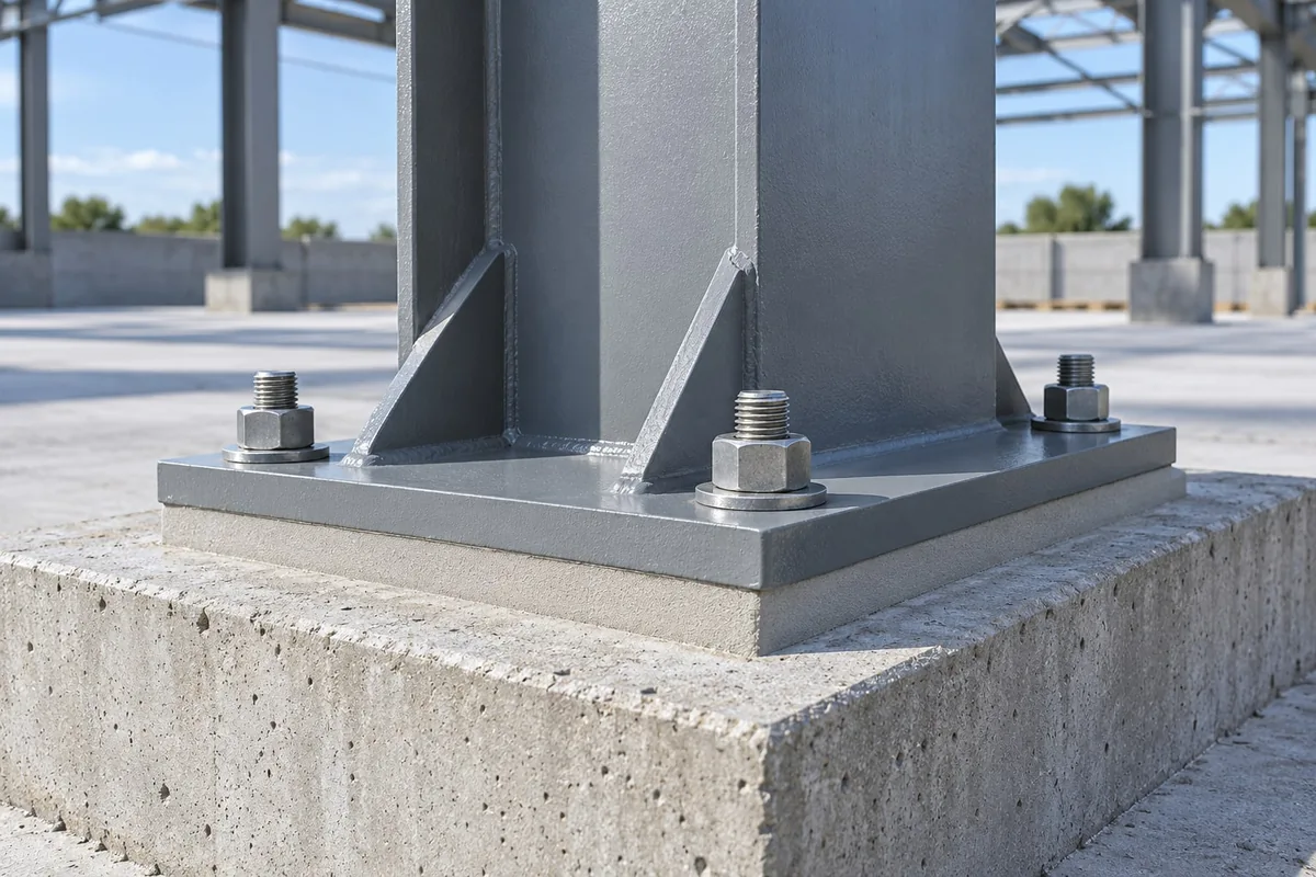
Grout beneath a column or machine base must fill a designed support gap within an engineered connection. High compressive strength alone is insufficient: the material must reach the bearing area and meet the installation acceptance criteria.
Before pouring, reconcile the engineer’s detail, the exact grout’s instructions and the contractor’s placement plan while the gap is still accessible.
Make sure the material has the right role
Tile-joint grout, floor leveller, repair mortar and bearing grout are not interchangeable simply because they contain cement.
SEED’s TENSYL Non-Shrink Grout guide identifies the NG 101 role as designed support gaps beneath baseplates, column bases and bearings. It also makes an important qualification: the product name alone does not establish a tested non-shrink classification. Request product-matched expansion evidence, strength evidence and the complete application instructions.
A specification may refer to a recognised grout standard, such as ASTM C1107/C1107M for packaged hydraulic-cement nonshrink grout. The project team must identify the required edition, test evidence and acceptance conditions. A standard named in a quotation is not a substitute for checking the supplied product.
If the real task is to create a smooth floor for a covering, use the separate floor-layer selection guide, rather than selecting a baseplate grout for its strength alone.
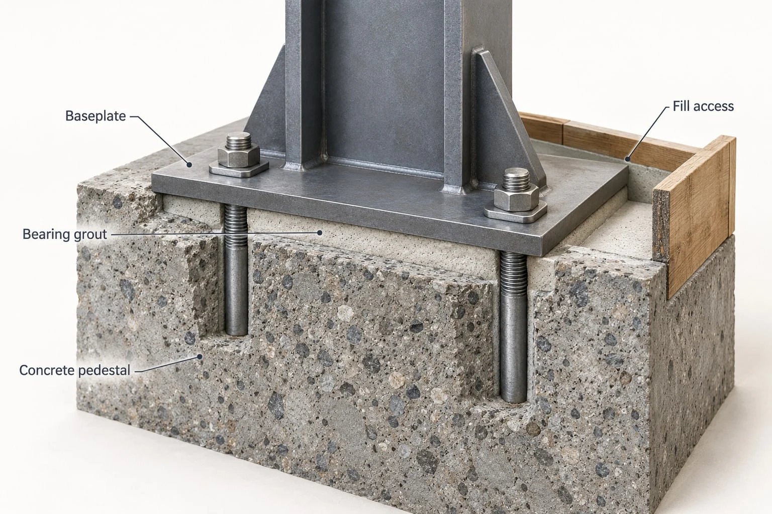
Start with the connection drawing
Before asking how many bags are needed, obtain a drawing or clear surveyed detail showing the foundation, baseplate, anchors, proposed grout bed and any levelling arrangement.
The pre-pour brief should identify:
- The supported element and its reference number.
- Minimum and maximum clearances beneath the plate.
- Plate dimensions, pockets, obstructions and proposed grout boundaries.
- The filling position, grout travel path and air-release locations.
- The equipment or structural loading programme.
- Responsibility for alignment, anchor details and loading approval.
Include vibration and other machine-specific service conditions before treating grout products as equivalent.
Do not calculate anchor capacity or approve a bearing arrangement from the grout’s compressive strength. Those decisions belong to the connection design, which includes more than the material placed in the gap.
Check whether the grout can reach the whole space
A narrow entrance does not guarantee that material can travel successfully beneath a large plate. Clearance, travel distance, obstacles, consistency and the means of placement need to be considered together.
The VELOSIT NG 512 manufacturer sheet, edition 4924, relates its grout’s travel to available clearance and gives product-specific placement guidance. It also explicitly prohibits using vibration to increase flow. Those instructions belong to NG 512; they must not be copied across to TENSYL NG 101 or another grout.
Ask the contractor to mark the inlet, path around obstructions and air outlets on the drawing. Difficult geometry may require a trial or revised engineered detail, not extra water on the day.
Prepare the interfaces and inspect them while visible
The approved method should address concrete and plate preparation, weak material, contamination, access and any required steel treatment.
Where the selected cementitious grout requires a saturated-surface-dry concrete substrate, that means a preconditioned surface without standing water. NG 512’s sheet specifies that condition for its concrete application. Use the selected grout’s own preparation instructions, including any required bond or strength checks. VELOSIT NG 512 technical data.
Photograph the prepared area and record unresolved contamination or foundation defects before enclosing it. Do not conceal unassessed concrete problems. See honeycombing assessment before repair if the support concrete contains visible voids or suspect areas.
Build formwork around the placement method
The formwork has to contain the grout while allowing the approved filling sequence. Check its stability, seals, cleanliness, inlet arrangement and air-release access. Keep release agents away from surfaces that must bond.
Sika Canada’s cementitious-grouting method statement illustrates why tight forms, clear vents, sufficient head and continuity of placement are considered together. It is a manufacturer-specific reference, not a universal installation recipe. Cementitious grouting of machine bases and baseplates, November 2017.
Assign formwork inspection and agree how grout arrival will be observed. Decide how the crew will respond to leaks, stalled flow or obstructions before mixing.
Estimate volume without confusing it with bag yield
Start with the actual three-dimensional grout space. A rectangular gap’s geometric volume is its plan area multiplied by its depth, but real installations may include pockets, changes in clearance, projecting shoulders and occupied space.
For illustration, a clear space of 0.6 m by 0.6 m by 0.04 m occupies 14.4 litres. These are not recommended design dimensions; pockets, obstructions, extensions and placing losses are excluded.
Convert the reviewed volume to bags using the exact product’s documented yield at the specified consistency. Do not divide by bag weight as if kilograms and litres were interchangeable. Record any allowance separately, with a reason, and confirm enough material is available to complete the planned placement.
Organise the pour as a continuous operation
Before work begins, check material identity, batch details, storage history, shelf life, mixing equipment, measured water supply and the time available for placement. Nominate the people responsible for mixing, delivery, placement, observation and records.
The specified consistency should be achieved within the product’s permitted water range. If the grout will not move as expected, investigate the method rather than improvising an unapproved dilution. The NG 512 instructions, for example, distinguish working conditions and application procedures for that grout. NG 512 technical sheet.
Log batch times, measured water, conditions, sequence, interruptions and outlet observations. Record deviations and who authorised the response, not just the finished appearance.
Keep curing and loading as separate decisions
Arrange the specified curing and protection before pouring. Account for site exposure; do not copy a routine from a different grout.
Agree the release criteria for form removal, alignment work, anchor operations and service loading before the pour. The engineer and, where relevant, equipment supplier should establish how the installed grout’s readiness will be verified. A published laboratory strength at a stated age does not by itself certify the actual connection.
The handover record should include the approved detail, product documents, preparation acceptance, placement log, specified test results and signed release. SEED’s NG 512 product page is a useful starting point for discussing engineered gaps alongside the TENSYL option, without assuming that their application limits are interchangeable.
Frequently asked questions
Does non-shrink mean the grout needs no curing?
No. The term does not replace the selected product’s curing and protection instructions or the project specification.
Can more water improve flow beneath a large plate?
Only adjustments expressly permitted by the matched instructions are acceptable. An inadequate flow path or clearance cannot be solved reliably by uncontrolled water addition.
Can one grout be used for every pump and steel column?
No. Check geometry, loads, vibration, exposure, access and release requirements for each application.
When can the supported equipment be started?
When the project’s acceptance and loading criteria are met and the responsible parties approve release. A hard-looking grout edge is not the acceptance test.
Sources checked 22 October 2026. The connection design and matched supplied-product instructions govern selection, installation and loading.